Description and application
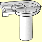
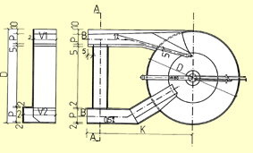
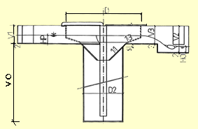
Vortex grit chambers are made of polypropylene. Usually they are constructed with a by-pass conduit, sand washer and air-lift pump, including valves for regulation and supply of pressurised air and water. Moreover, it is possible to equip the device with racks or fine screens *** (steel, stainless steel, plastic), with pressure air and water and with a machine removing of sand, with a container and control electronics. The Vortex grit chamber is shown in Figure 1, and technical parameters, dimensions and a weight for design purposes are shown in tables below.
Vortex grit chambers are used for removal of suspended solids of mineral nature (sand with grains 0,2 mm, clinker, slug and ashes, mineral dust etc.). Water inside a Vortex grit chamber is forced to lateral circulation and due to centrifugal forces, separation of organic particles from those with higher density occurs. This results in a simple operation because it is not necessary to remove the sand or to face problems with a raw sludge.

Vortex grit chambers are produced for a capacity ranging from 0,5 l/s to 150 l/s. Its smooth operation is dependent on a quality of hydraulic design. In case that you would need a professional assistance, we shall evaluate from the hydraulic point of view your project free of charge.
LP 03
|
|
|
|
|
|
|
|
|
|
|
|
|
|
|
|
|
|
|
|
|
|
|
||
|
|
|
||
|
|
|
||
|
|
|
||
|
|
|
|
|
|
|
|
|
|
|
|
|
|
|
|
|
|
||
|
|
|
|
|
|
|
|
||
|
|
Recommended DN 150 with a bottom slope of 1 % | ||
|
|
Recommended DN 150 with a bottom slope of 1 % | ||
LP 05
|
|
|
|
|
|
|
|
|
|
|
|
|
|
|
|
|
|
|
|
|
|
|
||
|
|
|
||
|
|
|
||
|
|
|
||
|
|
|
|
|
|
|
|
|
|
|
|
|
|
|
|
|
|
||
|
|
|
|
|
|
|
Recommended DN 150 with a bottom slope of 1 % | ||
|
|
Recommended min. DN 150 with a bottom slope of 1 % | ||
|
|
|
||
LP 07
|
|
|
|
|
|
|
|
|
|
|
|
|
|
|
|
|
|
|
|
|
|
|
||
|
|
|
||
|
|
|
||
|
|
|
|
|
|
|
|
|
|
|
|
|
|
|
|
|
|
|
|
|
|
|
|
|
|
|
|
|
|
|
|
Recommended DN 200 with a botom slope of 1 % | ||
|
|
Recommended DN 200 with a botom slope of 1 % | ||
|
|
|
||
LP 15
|
|
|
|
|
|
|
|
|
|
|
|
|
|
|
|
|
|
|
|
|
|
|
||
|
|
|
||
|
|
|
||
|
|
|
||
|
|
|
|
|
|
|
|
|
|
|
|
|
|
|
|
|
|
||
|
|
|
|
|
|
|
Recommended DN 250 with a botom slope of 1 % | ||
|
|
Recommended min. DN 250 with a botom slope of 1 % | ||
|
|
|
||
LP 30
|
|
|
|
|
|
|
|
|
|
|
|
|
|
|
|
|
|
|
|
|
|
|
||
|
|
|
||
|
|
|
||
|
|
|
||
|
|
|
|
|
|
|
|
|
|
|
|
|
|
|
|
|
|
||
|
|
|
|
|
|
|
Trapezoidal channel with a bottom width 10 cm and a side slope 1:1 | ||
|
|
Total width 40 cm in descent of 0,5 % or DN 300 with a botom slope of 1,2% | ||
|
|
|
||
LP 50
|
|
|
|
|
|
|
|
|
|
|
|
|
|
|
|
|
|
|
|
|
|
|
||
|
|
|
||
|
|
|
||
|
|
|
||
|
|
|
|
|
|
|
|
|
|
|
|
|
|
|
|
|
|
||
|
|
|
|
|
|
|
Trapezoidal channel with a bottom width 10 cm and a side slope 1:1 | ||
|
|
Total width 40 cm in descent of 0,5 % or DN 300 with a botom slope of 1,2% | ||
|
|
|
||
LP 70
|
|
|
|
|
|
|
|
|
|
|
|
|
|
|
|
|
|
|
|
|
|
|
|
|
|
|
|||
|
|
|
|||
|
|
|
|||
|
|
|
|||
|
|
|
|
||
|
|
|
|
||
|
|
|
|
||
|
|
|
|||
|
|
|
|
||
|
|
Trapezoidal channel with a bottom width 10 cm and a side slope 1:1 | |||
|
|
Total width 40 cm in descent of 0,5 % or DN 300 with a bottom slope of 1,2% | |||
|
|
|
|||
LP 150
|
|
|
|
|
|
|
|
|
|
|
|
|
|
|
|
|
|
|
|
|
|
|
||
|
|
|
||
|
|
|
||
|
|
|
||
|
|
|
|
|
|
|
|
|
|
|
|
|
|
|
|
|
|
||
|
|
|
|
|
|
|
Concrete piping DN 600 with a bottom slope of 1 % | ||
|
|
Concrete piping DN 600 with a bottom slope of 1 % | ||
|
|
|
||
Design of out-flow and in-flow channels can be changed individually. The external dimensions of a circular part of the Vortex grit chamber and height codes according to the table below are compulsory. Around the circular part braces with a width of 10 cm are welded in such a way, that the actual outside dimension reaches maximum D plus 20 cm. The Vortex grit chamber with the braces is embedded into concrete with minimum thickness of 30 cm.


(c) 2006, PARS Aqua, s.r.o.