
Flow Wastewater Measurement
Ing. Vrąecký Jan, Csc
May 2010
1.1. Equipment for continual flow measurementand it¶ selection criteria
1.1.1. Choice of measurement equipment
1.1.2. Comparison of flowmeters
1.2. Weirs
1.2.1. Sharp crested weirs
1.2.1.1. V notch weir
1.2.1.2. Rectangular weir
1.2.2. Broad crest weirs and wide broad crest weirs
1.3. Flumes
1.3.1. Parshall flume
1.3.2. Venturi flume
1.5. Q-h curve of channel and of measuring profile
1.6. Ultrasonic method
1.6.1. Doppler principal
1.6.2. Translation of the sonic image
1.6.3. Ultrasonic transmission
1.7. Magneto-inductive flowmeters
1.7.1. Full running profiles
1.7.2. Partial filled profiles
1.8. Electronic flow data convertors/processors
1.1. Equipment for continual flow measurement and it¶ selection criteria
Equipment for continual electronic flow measurement (flowmeters) consists of hydrometric profile, sensor and
electronic convertor/processor. Hydrometric profile is such a channel arrangement, that forces the water to
pass from subcritical flow over a critical depth to supercritical flow or it is prismatic channel/pipe
stretch, in which the cross section area can be described as a function of flow depth, constant in time.
Convertor/processor can be described as equipment that uses sensors (ultrasonic, pressure, induction sensors,
floats) to evaluate the variable measured quantity. Processor itself makes the statistical evaluation of the
discharge. Time series of the evaluated values and statistical parameters can be stored in the memory,
transmitted for further processing or directly used for regulation of connected pumps, samplers, alarms, flow
control units.
For the flow measurement within the sewer systems and treatment plants only selected types of flowmeters can
be used due to the specific quality conditions and range of flow of the waste water. The following flowmeters
can be applied :
- Sharp crested/broad crested measurement weirs with convertor/processor,
- Measurement in prismatic channels with convertor/processor,
- In low energy flow conditions ( low slope) or in locations, where the construction of weir/flume is
problematic, the ultrasonic flowmeters with direct measuring of velocity and depth of flow (ultrasonic Doppler
principle, translation of sonic image, ultrasonic transmission) or magnetic - inductive flowmeters (in
pressure and free surface conditions) are used,
- Combined measurement installations, consisting of appropriate combination of basic weirs and flumes (V notch
weir combined with rectangular weir or Parshall flume combined with long- crested weir, small Parshall flume
incorporated into the bigger one etc. are usually used in case of wider range of flows (for instance for
combined sewer system), data are evaluated by convertor/processor,
- For the measurements with lower level of accuracy the Q(h) characteristic (Chezy equation) of the channel
can be used for the evaluation of discharge (after verification of the roughness coefficient by hand metering
). Method of settling of Q(h) curve with bottleneck arrangement, enabling passing from subcritical flow over a
critical depth to supercritical flow, has a potential for higher accuracy. However, due to the limited
possibility to settle the parameters of the consumption curve experimentally in an accurate way, this method
is often less precise, data are evaluated by convertor/processor
- Other methods like orifice, siphon, filling and emptying of the reservoirs, momentum method, radar, chemical
methods are used only seldom.
1.1.1. Choice of measurement equipment
The choice of measurement equipment depends on various, in many cases antagonistic criteria. The following
criteria should be taken into account in selecting of the appropriate type of the flowmeter:
|
Criteria |
Decision parameters |
|
Financial aspects |
- in case of higher fees for spilling of wastewater the more accurate and thus more expensive
equipment is needed |
|
Local influences |
- climatic conditions (mountainsx lowlands x town x communication x wastewater treatment plant ) |
|
Utilization |
- stationary (for long term application) |
|
Character of flow |
- open channel ( e.g. channels, creeks ) |
|
Water quality |
- choice of equipment in accordance with the water quality ( aspect of erosion, corrosion, blockage, sedimentation, self-cleaning, incrustation, biofilm) |
|
Flow rate |
- design of flowmeter with appropriate flow range ( flow range estimate) |
|
Hydraulic conditions |
- the hydraulic conditions both on inflow and outflow should be acceptable in the whole range of
discharge, |
|
Energy loss |
- high -- sharp-crested weirs |
|
Accuracy durability Reliability |
- level of correpondance with the specific needs and application |
|
Instalation |
- accessability |
|
Influence on |
- influence of installation and operation of equipment on environment |
The choice of the optimal solution is not straightforward and depends on the level of knowledge of the
consultant. The optimal result can be achieved, when the team, comprising the investor, operator and
consultant is involved in the specification. This arrangement has a potential for the complex evaluation of
all the criteria and source information.
In the current conditions, when the spill fees are high, generally both the parties, producers of wastewater
and operators of recipients, have an interest to measure discharge in the most accurate and robust way. This
interest often leads to the installation of more expensive measurement equipment and to more frequent
calibration.
1.1.2. Comparison of flowmeters
For the rough orientation the comparison of the selected measurement equipment based on the selected basic
criteria, can be shown, as follows:
|
Measurement type |
Construction feasibilty |
Simplicity of calibration and checking |
Headloss |
Price
(remark) |
Type of wastewater |
|
Sharp-crested weirs |
no |
yes |
high |
medium |
mechanically treated water |
|
Parshall flumes |
low |
||||
|
Q-h curve |
yes (during the operation) |
no |
zero |
low |
raw wastewater |
|
Ultrasonic method |
yes |
higher |
Remark : price ranking for the discharge up to cca 200 l/s
Weirs , used for measurement purposes, are in principle sharp crested weirs and weirs with short/broad crest.
Sharp crested weirs consist of the thin wall , introduced in the channel perpendicular to the direction of
flow. The wall can be shaped in several different ways, the upstream edge of it always being sharp. The
discharge is recorded by the convertor/processor.
Among most often used weirs rank high V notch weirs with various central angles, rectangular weir, parabolic weir, trapezoidal and proportional weirs. The flow characteristics are influenced to the great measure by the flow characteristics in front of the weir. Basic disadvantage of the weirs is big headloss and low potential for prefabrication.
|
Advantages |
Disadvantages |
|
Easy and quick installation in the manhole |
Difficult and not economical prefabrication |
|
High precision of measurement |
Each weir is original with its own project |
|
Easy checking of the measurement precision |
Not applicable for the raw sewage |
|
High adaptability to the measurement range |
High headloss |
|
Extensive build up space |
|
|
High requirements for the calming of the velocity field |
|
Most frequent errors |
|
|
low quality of cutting out of the notch, the crest is not sharp (the thicknes is higher than
|
|
|
Faulty geometry of weir, wrong horizontal setting, defected crest |
|
|
The hydraulic preconditions are not met ( the flow trajectories are not well developed ( overflow crest is not far enough from the bottom, too narrow channel) |
|
|
The hydraulic conditions on the outflow side are not optimal (the overflow is influenced by the backwater) |
|
|
The space under the water jet is not connected to free air |
|
|
The wastewater flows under the weir construction |
|
|
The calming of the flow is not sufficient - waves, vortexes, not symmetrical overflow jet |
|
|
Wrong specification of Q= function(h) |
|
|
Space in front of the weir is logged by sediments |
|
|
Wrong zero setting (skewed setting of weir ) |
|
|
Not existing first calibration protocol in case of prefabrication |
|
Sharp crested V notch weir (extended measurement error - 3%) is preferably used in locations with high range
of discharge. With linear growth of overflow depth, the flow area grows in a quadratic way. The consumption
curve formula is Q = a . h2,5. It means, the overflow is extra sensitive to the change in the overflow depth,
i.e. the error in depth is transferred into the discharge calculation by power n= 2,5. Consequently, for the V
notch weirs more accurate electronic convertors/ processors should be used. Under condition of correct
overflow depth setting and the accurate formulation of the Q=function(h) equation the V notch weir can be
ranked among the most precise flow meters.
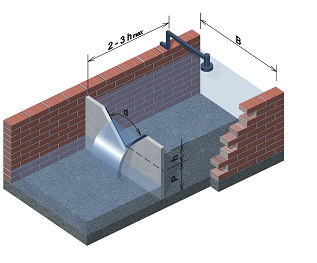 figure1
Construction of the weir and consumption curve :
The basic parameters are on the Figure 1. The axis of the notch must be vertical and in the same distance from
the side walls. When the velocity field is calmed down efficiently, the nappe shows full contraction and the
influence of walls, invert and inflow velocity is negligible. Consequently, the Q=fce(h) formula is stable for
the whole range of the overflow depths. When the contraction is not full, the walls exert influence the
Q=function(h), the effective overflow coefficient changes with the overflow depth, i.e. when constant overflow
coefficient for the whole range of flows is used, the extended measurement error is higher. Central angle of
the notch can be adjusted to the actual range of flows in the interval from 250 to 1000. The procedure of
setting the consumption curve formula and usage of V notch weir can be found in the corresponding ISO
norms.
Description of Figure 1:
h (m) overflow depth in 2- 3 m distance in front of the weir
note: influence of the inflow velocity is not taken into account
Q (m3/s) discharge
B (m) width of the inflow channel
P ..(m) height of the top of the weir crest above the bottom of the weir pool
Specific errors of the weir :
- vertex of the notch is not clearly cut, consequently the zero level is not defined well,
- the crest is not sharp, the weir is skewed,
- the central angle is not precise, the edge of crest is not flat,
- waves, bubble intrusion, not uniform velocity field in the measurent profile,
- the crest is placed lower than 5 cm above the maximum downstream water level.
Rectangular weir (extended measurement error - 4%) is preferably used in locations with settled range of
discharge. With linear growth of overflow depth, the flow area grows in a linear way. The consumption curve
formula is Q = a . h1,5. It means, the overflow discharge is sufficiently sensitive to the change in the
overflow depth, i.e. the error in depth is transferred into the discharge calculation by power n = 1,5.
Consequently, for this type of weir less accurate convertors/processors can be also used. Under the condition
of correct overflow depth evaluation and the accurate setting of the Q=function(h) formula the rectangular
weir can be ranked among the very precise flow meters.
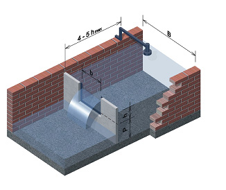 figure2
Construction of the weir and consumption curve :
The basic parameters are on the Figure 2. The wall of the weir must be vertical and the sides of the weir must
be in the same distance from the side walls. In case of suppressed rectangular weir (hawing no sides on the
blade) the crest ends up on the side walls, that are flat and overlap the weir min 0,5h in the direction of
flow. The weir should be located into the rectangular channel (only when the inflow velocity is sufficiently
low, it is possible to apply different profile shapes). When the velocity field is calmed down efficiently,
the nappe shows full contraction and the influence of walls, invert and inflow velocity is negligible.
Consequently, the Q=function(h) formula is stable for the whole range of the overflow depths.
When the contraction is not full, the walls influence the Q=function(h) and the effective overflow coefficient
changes with the overflow depth, i.e. when constant overflow coefficient for the whole range of flows is used,
the extended measurement error is higher. The procedure of setting the consumption curve formula and usage of
rectangular weirs can be found in the corresponding norms.
Description of Figure 2.
h-(m) overflow depth in 4- 5 m distance in front of the weir
Q (m3/s) discharge
B (m) width of the inflow channel
b (m ) width of the rectangular weir
P-( m ) height of the top of the weir crest above the bottom of the pool
Specific errors of the weir:
- the crest of the weir is not horizontal,
- the crest of the weir is not flat,
- the crest is not sharp, the weir is skewed,
- waves, bubble intrusion, not uniform velocity field in the measurement profile,
- the crest is placed lower than 5 cm above the maximum downstream water level.
1.2.2. Broad crest weirs and wide broad crest weirs
|
Advantages |
Disadvantages |
|
Not complicated shape of weir |
Difficult prefabrication |
|
Low cost implementation (structural modifications)- ramps are build in the channel |
Ramp flumes can be used with sufficient precision only for the pretreated wastewater |
|
Low need for drop in water level before and after the weir |
Each weir is original with its own project |
|
Easy checking of the measurement precision |
Accurate hydraulic calculation and accurate construction |
|
Lower requirements for the calming of the velocity field |
|
Most frequent errors |
|
|
Faulty geometry of the weir, skewed weir, damaged crest |
|
|
Not favorable hydraulic conditions on both the inflow and outflow side ( high slope, not uniform velocity distribution) |
|
|
Wrong specification of Q= function(h) |
|
|
Space in front of the weir is logged by sediments |
|
|
Not stable construction, possible erosion of the surface, when upproper material is used |
|
|
Wrong zero setting (skewed setting of weir ) |
|
|
Not existing first calibration protocol |
|
Broad crest weirs (extended measurement error - 8 %) are open-channel flow sections, where the bottom is
raised (in this case the flow trajectories are not parallel) (Figure 3) . Most often used is the Crump flume
(longitudinal profile of the raised part of the bottom is triangular). Due to the unstability of the flow
conditions the accuracy is influenced by many factors and the measurement error is higher.
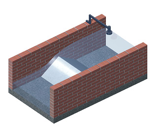 figure3
Wide broad crest weirs (extended measurement error - 6 %) %) are open-channel flow sections, where the bottom
is raised in a way, that the flow trajectories are perpendicular (obrázek č. 4). The flow characteristics are
more stable and the measurement error is smaller. Most often used type is the broad crest with rectangular
longitudinal section (sharp or rounded edge on the inflow side).
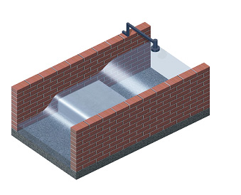 figure4
For the raw wastewater the ramp flumes are less suitable due to the sedimentation in front of the measurement
profile. When the space in front of the ramp is filled with sediment, the water level gets lower and the
overflow discharge is higher than calculated from standard consumption curve. This type of measurement is in
some cases used also for the wastewater measurements for the ease of installation, on condition that the space
in front of the ramp is regularly cleaned (sucking or washing away).
Flumes are open channel flow sections, which cause such a contraction of the crosssectional profile, that the
flow regime change from subritical to supercritical. The flumes can be devided into 2 types: Long-throated
flumes, where at least in some parts of the throat the flow trajectories are parallel and flumes without a
throat, where the flow trajectories are not parallel. Among the most famous flumes are Parshall, Montana
,Venturi , Saniiri, Palmer-Bowlus, Leopold -Lagco flumes, trapezoidal, U shaped and others. For their high
resistance against clogging/siltation the flumes are applicable for raw sewage with high content of suspended
solids. Above that the long-throated flumes are very resistant against the waves and unsteady velocity profile
and thus their accuracy is high. The measurement range of the flumes is high and the energy loss is low. The
installation can be typically arranged without higher extent of the structural arrangements.
|
Advantages
|
Disadvantages |
|
Not complicated shape of weir |
Lower measurement range than V notch weir |
|
Low cost implementation (structural modifications - prefab parts built in the sewer) |
Accurate hydraulic calculation and accurate construction is needed |
|
Low hydraulic fall needed |
|
|
Easy checking of the quality of measurement |
|
|
Easy to prefabricate |
|
|
Applicable for raw sewage |
|
|
Lower requirements for flow calming |
|
Most frequent errors |
|
|
Faulty installation of prefab unit ( skewed flume instalation, defected connection to on inflow or outflow side) |
|
|
Not favorable hydraulic conditions on both the inflow and outflow side (high slope, not uniform velocity distribution etc.) |
|
|
Not accurate dimensions of the prefab unit |
|
|
Not existing first calibration protocol |
|
|
Wrong zero setting (skewed setting of weir etc.) |
|
Parshall flume (extended measurement error - 4%) is specific type of long-throated flume (Figure 5, Figure 6).
Parshall flume is predominantly used in locations with stable range of flows (for higher range of flow the
combined Parshall flumes are used).
With linear growth of overflow depth, the flow area grows in a linear way. The consumption curve formula is Q
= a . h1,5. It means, the overflow discharge is moderate sensitive to the change in the overflow depth, i.e.
the error in depth is transferred into the discharge calculation by power n = 1,5. Consequently, for this type
of weir less accurate convertors/processors (and cheaper) can be also used.
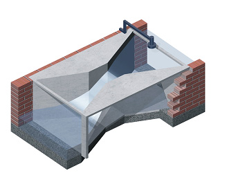 figure5
One of the advantages of this type of flume is the fact, that the depth is measured within the extent of
throat, where the velocity is already increased and the flow trajectories are more stable, also thanks to the
vicinity of spillway and shape of throttle. The solid particles transported by water tend to sediment
eventually in front of the measurement profile and the measurement is typically not sensitive to
sedimentation. During peak flows the suspended solids are washed away. This type of flume gives very precise
flow results on the condition the depth of flow is measured correctly.
 figure6
Flume construction and consumption curve:
The basic parameters are shown on the Figure 7 and at the following table.
|
|
P1 |
P2 |
P3 |
P4 |
P5 |
P6 |
P7 |
P8 |
P9 |
Qmin |
0,26 |
0,52 |
0,78 |
1,52 |
2,25 |
2,91 |
4,4 |
5,8 |
8,7 |
|
Qmax |
6,22 |
15,1 |
54,6 |
168 |
368 |
598 |
898 |
1211 |
1841 |
|
a |
0,0609 |
0,1197 |
0,1784 |
0,354 |
0,521 |
0,675 |
1.015 |
1,368 |
2,081 |
|
b |
1,552 |
1,553 |
1,555 |
1,558 |
1,558 |
1,556 |
1,560 |
1,564 |
1,569 |
|
B` |
30 |
34 |
39 |
53 |
75 |
120 |
130 |
135 |
150 |
|
hd/h |
0,6 |
0,7 |
|||||||
|
m |
9 |
10.6 |
19.1 |
49.0 |
81.0 |
146 |
183 |
231 |
252 |
|
W |
2.54 |
5.08 |
7.62 |
15.24 |
22.86 |
30.48 |
45.70 |
61.00 |
91.4 |
|
C |
9.29 |
13.49 |
17.80 |
39.4 |
38.1 |
61.0 |
76.2 |
91.44 |
121.9 |
|
D |
16.75 |
21.35 |
25.88 |
39.69 |
57.47 |
84.46 |
102.6 |
120.7 |
157.2 |
|
E |
23 |
26.4 |
46.7 |
62.0 |
80 |
92.5 |
92.5 |
92.5 |
92.5 |
|
L |
63.5 |
77.5 |
91.5 |
152.4 |
162.6 |
286.7 |
294.3 |
301.9 |
316.9 |
|
O |
5 |
5 |
5 |
10 |
10 |
10 |
10 |
10 |
10 |
|
S |
20 |
20 |
20 |
20 |
20 |
20 |
20 |
20 |
20 |
|
U |
24.8 |
28.6 |
49.2 |
69.6 |
87.6 |
100.1 |
100.1 |
100.1 |
100.1 |
|
V |
30.7 |
35.35 |
39.9 |
54.0 |
80 |
100 |
120 |
140 |
180 |
Consumption curve :
Q = a * hb / alternatively ha /
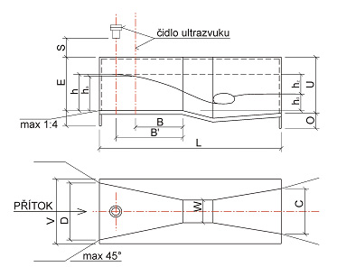
Description of the figure 7 and of the table
m...............(kg) weight of flume
hd/h..........( - ) maximal ratio of backwater influence
h ..............(m) water depth measured at the distance B´ in front of the throttle
Q .............(m3/s) dischrge
hd ............(m) water depth behind the flume-measured from the level of inflow
W aľ V .....(cm) dimensions of flume
When the strait stretches of channel needed for the flow calming are too short, the waves and non-uniform
velocity field can develop. As a result of the above mentioned and of the not accurate water depth reading,
the accuracy of measurement gets lower. The waves, when occur, do not have to be critical for the quality of
measurement. The measurement error should be in this case checked by independent flow evaluation (manual
metering by velocity probes or different method). When unacceptable measurement error is diagnosed, the
stabilization of the hydraulic situation must be carried out. For this purpose various types of flow
conditioners, baffles and floating baffles are used and alternatively, when possible, the bottom of the
Parshall flume is raised or new prefab flume is installed.
Specific errors of the flume:
- Consumption curve formula is settled for the water depth reading in exact distance from the throttle. When
the reading takes place in a different place, the formula is not valid.
- When a prefab unit without initial calibration is used or -homemade- product is used, serious deviations
from standard setup can occur
- Construction plans for flume prefab placing are not strictly followed,
- Flume is not placed horizontally.
Venturi flume (extended measurement error - 7 %) is a specific type of flume (Figure 8). The application range
is partly limited by slightly higher value of minimum flow (when the throttle width is the same as in case of
Parshall flume) and higher value of the extended measurement error. Ventury flume is not long-throated type of
the flume, consequently the flow trajectories are not so stable as in the case of Parshall flume. The water
depth measurement is located according to the design standards in long distance in front of the flume. Anyway,
based on the experience the acceptable distance for placing the water depth reading/sensor starts at 3h (3
times the overflow depth) in front of the flume. Exact dimensions, construction drawings and consumption
curves are typified (see Literature).
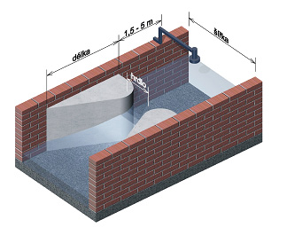 figure8
hd /h--...( - ) maximal ratio of backwater influence
h .---..(m) water depth measured at the distance B´ in front of the throttle
Q ---. (m3/s) discharge
hd ---..(m) water depth behind the flume-measured from the level of inflow
Hydraulic calculation for the Venturi flume setting is equivalent to that of the Parshall flume. However, the
calculation of the length of the calming zones in front and after the flume is considerably different. In
principle, the Venturi flumes need longer calming zones.
Specific errors of the flume :
- The width of the throttle is significantly different from the design/standardized value,
- Defective geometry of throttle (widening, narrowing),
- For the older types, constructed from low quality metal plates or without the steel bottom part, the
geometry can be seriously deteriorated by corrosion and water erosion,
- When a prefab unit without initial calibration or -homemade- product are used, serious deviations from
standard setup can occur
- Construction plans for flume prefab placing are not strictly followed (horizontal placement, vertical
setting of flume).
Combined flowmeters (extended measurement error from - 7 % to 10 %) are composed of 2 or exceptionally 3 weirs
or flumes ( Figure 9 and 10 ). This type of flowmeter is used in case, where high range of flows occurs, i.e.
usually in combined sewer systems. The principle of measurement consist of the measuring the most of flows by
the basic type of weir/flume. (sharp-edged weir, Parshall flume etc. ), where high accuracy of the measurement
can be reached and for only shorter time span the flow is measured by the combination of flumes/weirs, when
the accuracy is lower. The extended measurement error of the combined flowmeter for the overall yearly flow
volume is set as the weighted average of that of the basic type and of the combined one. When the design is
correct, the value of the extended measurement error must be smaller than 10 %, i.e. it this case the combined
flowmeter meets the Czech standards. Signifficant improvement in accuracy can be reached by the setting of the
Q=function(h) formula from model research.
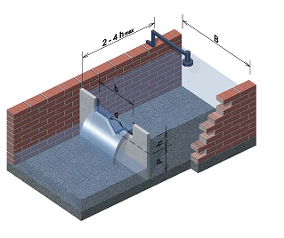 figure9
Types of combined flowmeters, that are more often used, are the following:
- V notch weir in combination with the rectangular weir (Figure 9),
- Small Parshall flume incorporated into the bigger one (as one prefab unit, Figure 10),
- Parshall flume combined with the wide broad crest weir etc.
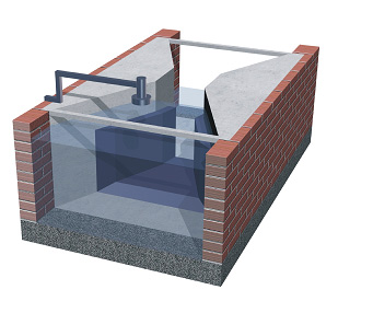 figure10
1.5. Q-h curve of channel and of measuring profile
Q-H curve of channel (extended measurement error -15% to 30 %). Setting of Q=function(h) is based on several
Q-h measurements (Figure 11). For a specific stretch of sewer or channel the consumption curve is set by means
of manual metering by velocity probe, volume method or by different way for several different flows. The
method can be used only in case of emergency (when different methods cannot be used) due to the limited
possibility of setting the curve in an accurate way and limited validity of the computed consumption curve in
time. The method generally does not meet the legal requirements. The advantage is the speed of installation
and zero energy loss of the instalation.
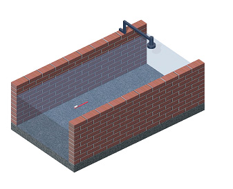 figure11
Note A: The accurate setting of the consumption curve means setting by a method, that is at least 4 times more
accurate than the needed accuracy of the consumption curve. As the curve is generally derived from the
measurements in normal operational conditions, this is feasible only seldom for the difficulties in making
accurate measurements (crossectional area, manual metering by velocity probe, installation of additional
flowmeter etc.) and impossibility of setting at least 5 different constant flows for certain time interval.
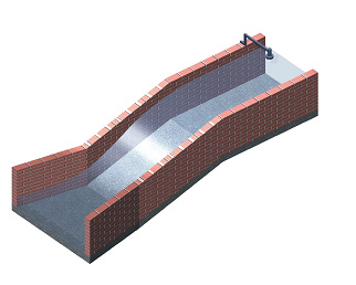 figure12
Q-H curve of measuring profile (extended measurement error - 7% to 15 %) , where the regime of flow changes.
In profiles, where the regime of flow changes from subcritical to supercritical, the consumption curve can be
settled by means of manual metering by velocity probe as the function Q -h ( Figure 12). Location for setting
of Q-h curve should be min. 3 hmax in front of the location of critical depth. Of course, the accuracy of
setting of the consumption curve depends on the accuracy of the flow metering (manual metering by velocity
probe), water level reading and stability of the flow (Note A). The applicability of the consumption curve in
time depends on the structural stability of the measurement location, i.e. of the place, where the flow regime
changes. The advantage of he method is quick applicability, low additional energy loss and potentionaly high
accuracy.
|
Advantages |
Disadvantages |
|
Quick instalation |
Difficulties in setting the consumption curve and hydraulic parameters |
|
Extent of channel adjustments is minimal |
Sophisticated choice of location |
|
Stabity of the consumption curve Q-h in time (in case of measurement profile) |
limited validity of the computed consumption curve Q-h in time (Q-h curve of channel) |
|
Acceptable accuracy (in case of measurement profile) |
Lower accuracy (for Q-h curve of channel) |
|
Zero energy loss (for Q-h curve of channel)Energy loss comparable with flumes (for Q-h curve of measuring profile) |
Extrapolation of water metering results beyond the metering range |
|
Applicable for raw sewage |
Difficult checking and calibration |
|
Low requirements for flow calming |
|
Most frequent errors |
|
|
Undefined or not precisely measured function crossectional area = f (h) |
|
|
Not favorable hydraulic conditions on both the inflow and outflow side (high slope, not uniform velocity distribution etc.) |
|
|
Wrong specification of consumption curve Q= function(h) |
|
|
Unstable hydraulic parameters in time (clogging , erosion, destruction, freezing etc. ) |
|
|
Unsuitable location (problematic extrapolation of water metering results beyond the metering range) |
|
|
Limited possibility of access, checking and calibration |
|
|
Not precise information about the status of the measurement profile |
|
|
Wrong zero flow setting |
|
|
Not existing first calibration protocol |
|
To summarize pros and cons for both the methods, it can be concluded, that their application depends primarily
on the quality of design, i.e. proper choice of location, proper setting of flow area as a function of water
depth, correct setting of zero flow level, proper consumption curve and measurement range setting.
Ultrasonic method - Doppler principal (extended measurement error - 3%). Electronic flowmeter measures
directly the flow velocity above the sensor, which is usually located on the bottom (Figure 13). For the
evaluation of the flow velocity the change in frequency between the signal transmitted from the sensor and
reflected back from the particles floating in wastewater is used. The processor evaluates the energy of the
reflected frequencies and calculates the average flow velocity of the floating particles.
 figure13
The evaluated value is the average velocity of floating particles in specific space above the sensor. The
water depth is measured by the ultrasonic sensor (fixed above the water surface) or alternatively by the
pneumatic or piezomentric sensor (different producers). Discharge is calculated from the known channel
geometry, from measured water depth and from the velocity of particles, that is taken as the average water
velocity in the whole profile. Due to the above mentioned simplification the calibration for different flows
(water levels) is needed after installation. This type of flowmeter is very easy to install, however its
reliability is lower due to the difficult calibration (Note A in the above text), to the clogging of the
sensor and to potential changing of the calibration coefficients in time.
1.6.2. Translation of the sonic image
Method of translation of the sonic image (extended measurement error -3%) is based on the direct measurement
of the point velocity values of the floating particles and of the water depth. At the bottom of the channel
the ultrasonic sensor, measuring the point velocity values of the floating particles and water depth (Figure
13), is placed. The velocity sensor transmits the ultrasonic signal in short time span and records the
spectrum of the sonic echo. Using the correlation method of evaluation of the reflection images the length of
translation between the individual sonic images is calculated. From the known interval between the signals the
point velocities are calculated. The vertical location of the measured point velocity is evaluated from the
propagation speed of the ultrasonic signal and the lag time of echo. In this manner 16 point velocities are
measured above the sensor. For more detailed description of the velocity field in the measurement profile 3
transmitters-receivers are built in the sensor (one in vertical direction and other 2 symmetrically shifted
from vertical). In dependence on the channel geometry and the number of used sensors the flowmeter evaluates
the point velocities in 50 to 70 % of the active flow crossection (point velocities in the channel -corners-
are extrapolated). The instantaneous total flow can be calculated by volume integration of the flow body,
created by the flow of particles in the flow profile in 1 second . The new method has a good potential for
application, especially because relatively cheap sensor, placed directly in the flow profile, is applied. The
price is actually high thanks to expensive software accessories and research costs.
 figure13
Corresponding to the above mentioned, i.e. because the velocities are evaluated only in part of the active
crosssection, the on-site calibration is again essential (manual metering with velocity probes).
Ultrasonic transmission (extended measurement error - 3% to -10 %) is a flow metering method based on the
evaluation of the time lag of the ultrasonic signal ( Figure 14). On the opposite sides of the pipe or channel
the ultrasonic transmitters/receivers are placed. The sensors are shifted to each other in the direction of
flow. The flow meter measures the difference between the time lag of the ultrasonic signal propagation against
the direction of flow (the flow velocity prolongs the travel time of the signal) and that in the direction of
flow (the flow velocity shortens the travel time of the signal). The known distance between the sensors and the
difference between the the time lags are input values for calculation of the average profile velocity. The
average profile velocity and the flow profile give the instantaneous flow. This type of flowmeter is produced
both for the pipes and channels. Variability of extended measurement error depends on the type and application
of specific product. Flowmeters , applied from the outer side of the pressure pipe, do not need any
supplementary fitting. Anyway, the measurement error of this type of equipment is higher. Flowmeters with the
sensors, having contact with the fluid, show greater accuracy of measurement. Nevertheless, the stability of
both types of measurement is low, above all because of the limited extend of coverage of the velocity field (not
all the velocity field is covered), because of possible silting and incrustation of pipe near the sensor,
because of excessive amount of suspended solids (generally the limiting value is max 10 mg/l ) and bubbles,
temperature stratification etc.. The metrologic checking of the flowmeters is not straightforward and calls for
the construction of check point, where the function of the equipment can be verified (most often by manual
metering by velocity probes). This type of equipment is usually used just for the operational, quick flow
checking (from outside of the pipe) without the need for the guarateed measurement with extended measurement
error up to10 %.
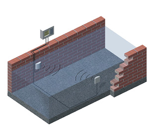 figure14
Nowadays there is measurement equipment on the market, aiming at minimizing the negative features of different
ultrasonic measurement methods by combining the measurement principles. Ultrasonic sensor is combined and is
able to evaluate the velocity, using both Doppler and transmission principle. Processor switches the function
of the sensor to arrange for the best accuracy of the resulting measurement.
|
Advantages |
Disadvantages |
|
Extremely quick instalation |
Higher price of electronic components |
|
Minimal channel modifications |
Shorter operation time compared to the structural objects |
|
Zero energy loss |
Difficult checking and calibration |
|
Also non-Newtonian fluids can be measured |
Velocity of suspended solids is measured, not of the water particles |
|
Velocity sensor is under water |
|
|
The setting of the electronics is unstable in time |
|
Most frequent errors |
|
|
Unsuitable measurement profile ( too high or low Froud nebo Reynolds number) |
|
|
Wrong flow velocity calibration |
|
|
Not precisely measured function crossectional area = f (h) |
|
|
Wrong zero flow setting |
|
|
Unsuitable quality of wastewater ( the quality of measurement is not usable , when the sensor is clogged or bubbles appear in the vicinity of the sensor) |
|
|
Not stabilized profile from the construction point of view |
|
|
Uncritical trust in the sensor and evaluation software perfection |
|
|
Not existing first calibration protocol |
|
1.7. Magneto- inductive flowmeters
Magneto- inductive flowmeters are based on the physical effect described by the Faraday law, i.e. on the
electromagnetic induction. The electric conductor is the moving fluid and electromagnetic field is constituted
by the coil, surrounding the pipe. Voltage is induced between the stainless steel sensors, located on the
opposite sides of the pipe, by the fluid flow in the direction perpendicular to the electromagnetic field.
Processor screens for the valid results and using the moving average method calculates and records the flow
values.
|
Advantages |
Disadvantages |
|
High accuracy of measurement |
Difficult checking |
|
Not prone to sedimentation - stability of operation |
Shorter operating life compared to the structural objects |
|
Zero energy loss |
Difficulties in checking of operation |
|
Ability to measure in both directions ( for accuracy the speed must be higher than 0,1 m/s ) |
Sensors are under water - acute danger of loss in sensitivity (automatic sensor cleaning) |
|
Usable for fluids with conductibility higher than 5 mS/cm |
The setting of the electronics is unstable in time |
|
Also non-Newtonian fluids can be measured |
Certified range of measurement (
|
Most frequent errors |
|
|
Unsuitable measurement location ( high - low velocity, non-uniform velocity field, bubbles) |
|
|
Unsuitable fluid |
|
|
Wrongly defined area of pipe or channel or incrustation |
|
|
Not existing first calibration protocol |
|
|
Unappropriate servicing, incrust, biofilm and sediment removal |
|
Magneto- inductive flowmeters for the full running profiles (extended measurement error 0,6 to 2 %) are used
for the conductive fluids flow measurement in closed profiles DN 10 - DN 1000. The prerequisite of the method
is full running pipe, i.e. pressure pipe behind the pump or inverted siphon constructed on purpose on the
gravitation sewer pipe. Usually special longer manhole is constructed for the placement of the flowmeter and
the setting itself is arranged for the cleaning (the inverted siphon is generally prone to clogging). Maximum
speed in pipe is generally limited up to 1,2 m/s (standard measurement profiles show for Qmax hydraulic loss
up to 0,1 (Z - 0,1 m).
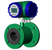
Magneto- inductive flowmeters for the partially filled profiles (extended measurement error 3 to 4 %) can be
used for the conductive fluids flow measurement in open channels or partially filled pipes. The sensors for
voltage induction are located on the bottom or on sides (board or point arrangement). The flow velocity is
measured between the sensors - so in case of the point sensors (so called -mouse- on the bottom) the velocity
is measured just in one place in the vicinity of the sensor and the average flow velocity is estimated based
on the usual shape of the velocity distribution in the profile with sufficient length of uniform flow
conditions. The water depth is measured by level meters (ultrasonic, float, pressure, inductive, contact, i.e.
based on submersion of point electrodes, sensors). The magneto - inductive flow meters are applicable just for
small range of velocities. Minimum velocity should be bigger than 0,1 m/s and maximum velocity is ruled by the
Froud number limitation up to 0,6. Taking into account the sensitivity to silting, just estimation of the
average flow velocity, higher price of unit and other factors, it is obvious, that this method is applied just
exceptionally.

1.8. Electronic flow data convertors/processors
Electronic flow data convertors/processors evaluate the flow data and record the data in time sequence.
Ultrasonic and magneto-inductive flow meters are usually supplied as one unit, comprising both the sensor and
processor, and their functionality is rather specific for the different product. For the other types of
flowmeters various types of level sensors and flow convertors/processors can be used. Nevertheless, each flow
convertors/processor manufacturer uses specific sensors on the long-term basis and changes them just as a
result of their innovation.
Water level sensors
For the water level metering the ultrasonic, float, pressure (piezoelectric and bubble method) and inductive
sensors are commonly used. The float method is the most precise for sure, unfortunately it ranks among the
methods using the contact with medium. The water level metering, based on the direct contact with wastewater,
is always prone to the incrustation, biofilm slime growth and silting. As the result of the above mentioned
are the contact methods (float, pressure) more demanding from the operational point of view. The contact
methods are not commonly used due to the technical complexity and generally higher price (for instance contact
steel pin is periodically dropped down to the water surface). For the operational ease and safety the
ultrasonic level meters are primarily used nowadays, regardless of their lower accuracy, compared to the float
sensors.
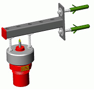
Ultrasonic sensors
The sensor is composed of the transmitter and receiver of ultrasonic waves. Based on the known sound velocity
in the air (with temperature correction) and time lag of received signal the distance from transmitter
/receiver to the water surface is calculated. From the known elevation of the transmitter/receiver and the
measured distance the depth of flow is calculated. As the measuring of time lag has a limited sensitivity, the
sensor is not able to measure within certain distance from the transmitter/receiver (in most cases up to 20
cm), i.e. the -dead measuring zone- exists. Accordingly the sensors should be placed at minimum 20 cm above
the maximal water level. The transmission angle of the sensors varies from 30 to 70, depending on the sensor
size and manufacturer. The sensor output is electrical, some producers of processors apply the signal
digitalization in/near the sensor, which gives the metering higher stability and the potential to place the
processor into longer distance.
Important features:
- Transmission frequency ( the higher the more accurate , but less stable ),
- Temperature compensation for the sound velocity (external temperature sensor),
- Electrical safety of sensor - min IP 67,
- The more advanced sensors are provided with the evaluation software (removal of fake side reflections,
reflections from stagnant waves etc.),
- Stability of the measuring in time ( some products show unstability of parameters in time),
- The deviation of the measurement is in case of more precise sensors up to 1 mm, in case of standard ones up
to 2 mm, however also the sensors with the deviation up 5 mm can be found on the market (valid for the sensors
with the measuring distance up to 1 m),
- ability to eliminate the effect of foaming and waving on the water surface.
Assessment of the ultrasonic sensor output:
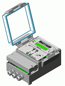
The idea behind the currently produced convertors/processors is to meet the legislative standards in their
basic setting with further possibility of functional upgrade to comply with the measuring requirements in
specific place of application to maximum extent. The basic setting includes the indicator of the total flow
volume as well as the indicator of total time of operation. For the ease of checking and calibration the
measurement units are almost always provided with the indicator of actual water depth and flow and
occasionally also by the time of actuation, total time of faulty readings and the memory for storing the time
series of flow. The common output is electric, and in some cases also digital or pulse. For the secluded
localities (without electricity) are some types of the measurement units equipped with batteries or solar
panels - their operation is due to it strictly autonomous. The modern telecommunication technology enables the
measurement units to be fitted with the wireless data transmission within acceptable prices. In the course of
selection of the measurement unit the features of the units should be compared.
Important features:
- sufficiently big, well -arranged and accordingly lighted display,
- warming of display for temperatures under -150C,
- user friendly and accessible keyboard of the unit,
- sufficient electrical safety of the unit ( min IP 55 ),
- potential for the pump, sampler, aerator etc. control,
- quality of the software for the screening and evaluation of collected data,
- ease of the operation of the unit and ease of using the operation manual ( not user friendly manual usually
indicates lower operation standard of the unit),
- potential for self - calibration,
- password to prevent unauthorized users from operating the unit
- robustness of processor, is it possible to repair it-, service,
- data about the producer ( extent of production, service, economical stability).
- Errors of the electronical processing
- wrong water depth processing,
- wrong zero setting (not appropriate work with elevations),
- not correct linearization ( right zero setting, but the difference between the real value of depth and unit
reading occurs for non zero depths),
- influence of the air temperature (units with the metering of temperature should be used),
- influence of the vapour condensation on the sensor or biofilm growth on the sensor,
- the sensor is not positioned vertically,
- the sensor is located out of the determined flow profile, for which the consumption curve is valid,
- the sensor is not well fixed (translation, turning of sensor),
- consumption curve is not calculated well,
- improper protecting of cabling (against rodents),
- error in recording of the flow values (error in time, error in operation time recording, error in
backup),
- clogging of the flow profile with consequent backwater effect (error in sewer operation),
- calibration protocol is missing.
2. Literature
1. Water Measurement manual, United States Depaertment of the interior Bureau of Reclamation Denver, Colorado
1967
2. Wastewater engineering , Metcalf and Eddy,INC , Third Edition 1991, ISBN 0-07-100824-1
3. Zákon O vodovodech a kanalizacích č. 274/2001 Sb.
4. Zákon O vodách č. 254/2001 Sb.
5. Zákon O metrologii 505/1990 Sb. ve znění zákona č. 119/2000 Sb. a zákona č. 137/2002 Sb.
6. ČSN ISO 1438 měření průtoku pomocí přelivů a Venturiho ľlabů
7. ČSN ISO 4360 Měření průtoku pomocí přelivu trojúhelníkového průřezu
8. ČSN ISO 9827 Měření průtoku pomocí proudnicových přelivů trojúhelníkového průřezu
9. ČSN ISO 4374 Měření průtoku pomocí přelivů se ąirokou korunou
10. ČSN ISO 8333 Měření průtoku pomocí přelivů se ąirokou korunou tvaru V
11. ČSN ISO 38 46 Měření průtoku pomocí přelivu pravoúhlého průřezu se ąirokou korunou
12. ČSN ISO 9826 Měření průtoku pomocí Parshallova ľlabu
13. Měrné objekty Venturiho ľlaby , Typový podklad Hydroprojektu Bratislava 1962
14. Metody měření průtoku v potrubích malého průměru , Hoření Petr, Závěrečná zpráva VÚV Praha , 1965
15. Patočka, Hydraulika , Vydavatelství ČVUT Praha 1, 1975
16. Měření průtoků odpadních vod -učební pomůcka, 11. 2000, I . Bémová , Radka ©vecová, Výzkumná zpráva VÚV
TGM 2002
17. Vypracování aplikace rozhodčích metod pro měření průtoků, 11. 2000, I . Bémová , Radka ©vecová, Výzkumná
zpráva VÚV TGM 2002
(c) 2010 PARS Aqua, s.r.o.